Composing objects and building blocks using openScad
- Carlos Gustavo Merolla

- Dec 5, 2020
- 7 min read

Motivation, the best driving force
If you read the first post on openScad you could be like ... OK, a couple of shapes. Let me say that my expectations when I started exploring Machine Learning were huge, it seemed to be a revolutionary technology from Mars! However, I felt a bit disappointed after knowing the details, it is effective, however, it is over-hyped. I think Elon Mask and its claims about AI conquering the world were ... exaggerated, don't get me wrong, ML and tinyML are effective for concrete uses.
Regarding openScad I went the opposite way, saying OK, just a few solids on my screen, however, after getting into the details, I got quite excited about it. Specially for me, a software engineer used to deal with abstract things, to see something getting real from a simple file was a new world. The bottom line: you can achieve really useful things with this software and 3D printing (I will post about 3D printing as soon as I can because 3D printing means to me the democratization of fabrication, at least, in small scale).

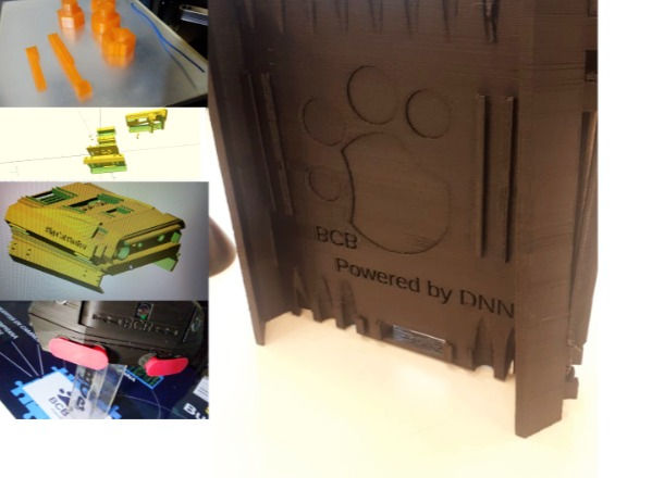
What you see in the upper left corner of the image is my first openScan design, as I learnt more about it I was able to do really complex and reusable designs; so the next few posts will be focused on the features openScad has to allow you to handle complex design easily.
Combining solids
As I said in the former section you can build complex designs by using these three simple shapes, if not, you can always design your own polygons as we will see later. openScad allows you to perform several operations with shapes in order to create more complex ones, the two common operations are union and difference. Union allows you to merge two shapes (only if they are in contact) and difference will create a new shape without the parts that are in contact, the opposite as union. The designs on the previous picture were made using these two operations. (and a few more that we will also explore later;))
Here you can see two (annotated) examples:
union()
{
    $fn= 360;
    sphere( 14 );
    cylinder( h=20, r= 5 );
};


// Things to notice here:
//
// 1)- If you want to specify a global face number setting
//     just use the system variable $fn, no need to specify
//     that in every primitive call
//
// 2)- Now you have a composite solid made of two.
//
// 3)- The syntax for union uses a couple { } to specify
//     all the shapes you want to merge, in this case, an sphere //     and a cylinder
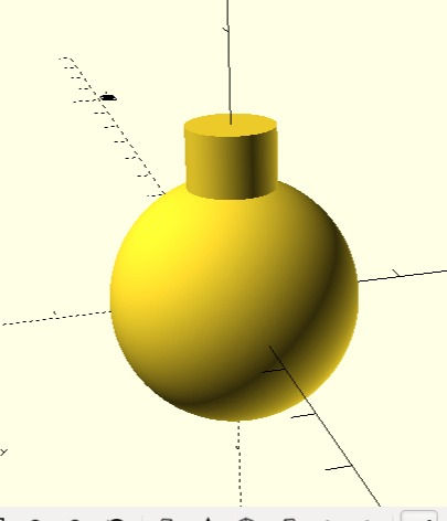
The result of this script once you hit the render icon will look like this:

The difference primitive does the opposite:
difference()
{
    $fn= 360;
    sphere( 14 );
    cylinder( h=20, r= 5 );
};

// Things to notice here:
//
// 1)- The sphere now has a hole!
//
// 2)- Now you have a composite solid made of two. Note
//     that the resulting object doesn't contain the area were
//     both shapes were in contact.
//
// 3)- The syntax for difference uses a couple { } to specify
//     all the shapes you want to intersect.
//
// 4)- Depending on your machine, you could start noticing the
       performance detriment by using more faces.
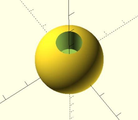
After rendering this script you will get something like this:

There are your first tools, from now on, all these things will be empowered by two characteristics of openScad, the control flow primitives and the modules. The first ones will allow you to do things according to certain conditions and also you will be able to do things in a repetitive manner. The second feature will allow you to organize your work and make it more re-usable for other designs and even other users.
Flow control
The previous examples are functional, however, to design complex things it would get really hard to achieve if you have to specify shape by shape. That is one of the most nice things about openScad, you have flow control sentences to make decisions (at compile time) and repetitions and they are quite similar to the ones used by C.
Suppose for a moment you want to do a box for a device, and you want it to have some kind of ventilation outlets (no too good for outdoor use), instead of specifying each outlet you will use the for sentence, and yes, it works just as the for you find in C and many other language, however, it has some specialized forms. The common syntax is as follows:
for ( variable= [start : increment : end ] ) … your commands;
So far, the examples I presented executed one line after the other in order, now, this sentence will allow you to repeat commands until a condition is reached. The condition could mean iterating each value on a vector (a list of values) or repeating the commands a given number of time. In the former format, the for sentence will start setting the variable (a name for storing values) with the initial value you specified and it will increment its value by the given increment until the variable reaches the end value, each loop will repeat the commands you specified in it. So far, we have used number as parameters, however, you can use variable names, take a look at the following example:
// Example 12, repetition

difference()
{
    cube( size= [30, 50, 5] );

    for ( v_outlet= [5 : 10: 50] )
    {
        translate( [10, v_outlet, 0] ) cylinder( h= 5, r= 3 );
    }

};


// Things to notice here:
//
// 1)- If you render this shape with the >> button you will
//     see a weird shadow, that is because the cube height
//     and the cylinder height are the same and >> runs
//     a fast rendering, to see the accurate rendering you
//     have to hit the I button.
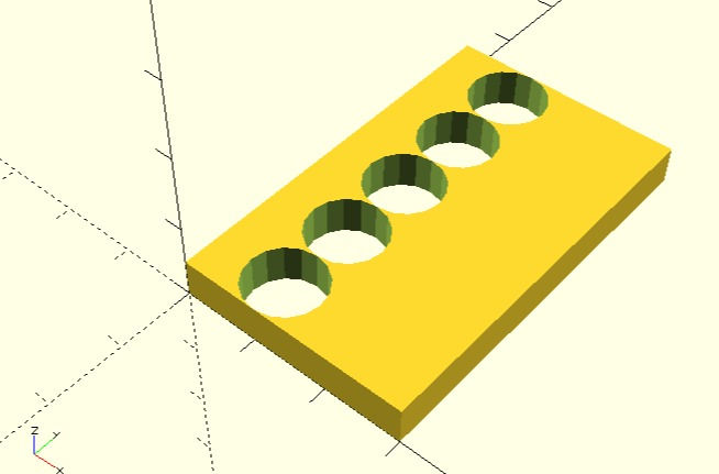
By running this example, you will see something like this:

Handy, right ? commercial software has these repetition functions, however, the price for those software packages is high, so, if you are in the position of supporting openScad, go to the link page, you will find the openScad link and support them.
Accordingly as we advance, I will show you a few more flow control sentences, now, let's move to the other important concept.
Modules and files in openScad
As you can see with a few primitives and sentences shown by now you have plenty of tools to do useful things, so useful that they can be great for other people as well. Either if you want to share your designs or they get more complex over time, there is a way to keep things clean and reusable; openScad uses an old practice in software engineering and that is … modules.
A module is a kind of set of commands put together under a given name. Modules can also have parameters that will make your designs suitable for other uses or users. As you saw in the openScad primitives, your modules can have parameters even with default values too.
Just as a context, suppose that you want the cover shown on the last example to be more... flexible. For instance, you should want square outlets or circular ones, or even, you would like to leave open the diameter and spacing of the ventilation outlets. Of course you can do that by modifying what you already did, whoever, building a module will bring you more flexibility and manageability for your designs, remember that a big problem is solved by solving small parts. Modules involves two things, the first one is its definition and the second one, its invocation to do what it is supposed to do. The syntax to define a module is as follows:
module module_name( [ parameter [= value],  ... ] )
{
	your sentences;
}
module_name is the name you want to give to your module, it is a good practice to use a verb an a noun, even a prefix, however, that is up to you. The [ ] in the parameter list means that all things contained between the two square brackets are optional, i.e. you can have modules with no parameters or parameters without default values. The .... means that you can have an arbitrary number of those definitions. Here is an example of a module definition for the former script:
// Example 13
// Module definition

 module UTIL_render_plate ( vent_radio= 3 )
{
    difference()
    {
       cube( size= [30, 50, 5] );

       for ( v_outlet= [5 : 10: 50] )
       {
           translate( [10, v_outlet, 0] )
                      cylinder( h= 5, r= vent_radio );
       }

     }
 }

 // Things to notice here:
 //
 // 1)- We defined the module with 1 parameter, the radius
 // 2)- We replaced the hard-coded value 3 with the new parameter
 // 3)- The parameter has a default value ... 3
Now, if you render this script you will see something like this: NOTHING!
You need to invoke the module to do its job as any other openScad primitive, if you write this:
// Invoked with no parameters, vent_radius will have the default // value
UTIL_render_plate();
You will get the same shape we rendered before, now, if you customize the radius and you write this:
// Invoked with a specific parameter
UTIL_render_plate(5);
You will get this shape! Your design now can be customized!

Noticed that the module is invoked without specifying the parameter name, we use just the value, we could have used:
UTIL_render_plate(vent_radius= 5);And it would produce the same shape. Compilers tend to analyse parameters by their position in the list, as we are using one single parameter, there is no chance that the compiler can get confused about what argument or parameter we are trying to set.
Modules and files:
To make these features useful, you will have to save your module definitions (only the definitions) in a file, for instance, UTIL.scad; you do so by clicking in the save icon; you should put related modules definitions (only) in the same file, so, each time you need to use or share your designs you will simply do as follows:
// Include the module definitions from your libraries
include <UTIL.scad>

// Invoke the modules as needed
UTIL_render_plate( 4 );
On the next posts, we will keep exploring modules and more flow control sentences and primitives to make your designs more re-usable and complex.
Stay Tuned!


Comments