Introduction to 3D modeling using openScad
- Carlos Gustavo Merolla

- Jul 8, 2020
- 7 min read
Updated: Dec 3, 2020

Introduction
The WildEdge site is not meant to be a cluster for random tutorials; every publication in this site has a common objective, to provide you with tools to build something useful, ideally for nature or biodiversity conservation; 3D design is a major tool because, your devices will need enclosures and trying to buy custom made cases is really expensive when done in low quantities, so, 3D printed cases are a good choice and reliable enough, even non-toxic for the environment.
The first posts will introduce concepts and information about openScad which is the software I use to make my own designs. Right now, I am working on a Smart Collar and I plan to release parts of it as open source, so the examples will be oriented to generate the case for a GPS and LoRa Smart collar! As we advance, the Smart cameras cases will be used as references too, the cameras won't go open source though, at least the ones I use for surveillance purposes.
So, lets start digging into openScad and 3D design.
openScad Basic Concepts
This is how the new openScad (version v2019.05) looks like:
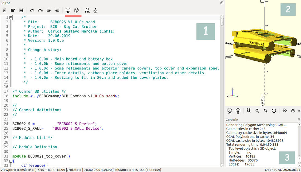
Basically openScad has three windows, the one at the left [1] is where you write the script or code, on the upper right windows [2] there is a rendered figure, that is what your code produced and finally, the small console [3] where you can see warning and some information about your design. Needless to say you can hide, resize and locate windows as you want.
The first thing to notice is that the rendering window has three axis (X, Y, Z) and that’s the basic concept of any 3D software. You will work with coordinates over those axis to position or translate your parts, the origin is 0, 0, 0, expressed as a vector ( [0, 0, 0] ) and sometimes it is convenient to locate objects there and then move them to other places, specially if you play with rotations, believe me, you can get really confused at the beginning while rotating objects far from the origin.
openScad has a few simple elements you will have to learn. openScad has some primitives to position things, draw (the proper word is render) basic shapes and some control structures like the ones you can find in C (if, for, etc), we will cover them all.
As you can see in the picture you can include comments a la C and C++, include other files where you could have common definitions but the key elements of openScad are the modules. Modules are a kind of function where you define reusable things, modules can have parameters which is quite convenient for reusing components. As an example of the former you could have a module to render (or draw) a screw and have a few parameters about the size of it, another handy thing is that parameters can have default values.
To start with something simple, we will drop a few commands to see what happens. Make it sure you have openScad properly installed and start a new design. On the code window just write:
cube (size= [10, 10, 10]);Then hit the icons highlighted in red on the figure above and you will see your cube rendered in the screen. That Icon will do a fast rendering, if you want the final rendering with the icon next to it. What is impressive about this is that you can already generate a 3D printable design, hit the STL icon and that file will be ready to be sent to Cura or any other 3D printing software (this version includes the function to send the design to the printer but I didn't test it yet). If your table is not stable, now you have a simple 3D printed solution!
There are few things you can render, examples of that are cylinders and complex polygons where you can specify each point of them. In these series of posts I will share some information and findings to help you make functional cases or part for your devices. If you are curious and anxious like me, you can find a cheat sheet right here.
Coordinates system and translations
As mention before, openScad uses 3 axis as any other 3D software, X, Y and Z being [0, 0, 0]
The origin point. The former example will draw a cube, whoever it falls into the positive quadrant of the space; this could led to some confusions at the moment of rotating solids, with that in mind, openScad offers the translate primitive that allows you to specify where the solid must be drawn.
// Example 1, drawing a cube
cube( size= [10, 20, 10] );


// Things to notice here:
// 1) the two slashed as comments just in C++
// 2) the cube is rendered on the positive quadrant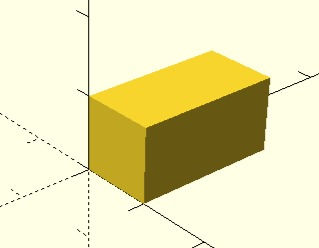
The syntax for the translation primitive is as follows:
translate( [X, Y, Z] ) your command;It is strongly recommended to use the [0, 0, 0] as a initial reference and then move your objects to the desired position; besides specifying the location, you can also specify a rotation for you shape or groups of shapes, for that, the rotate primitive will allow you to specify and angle for one or the three axis, the syntax is similar to the one used for translate primitive.
Rotate( [X, Y, Z] ) your command;This time, instead of specifying coordinates, you are going to specify angles. It is common to use this two primitives together, here are some examples to see the affects of translations and rotations, just type the code and hit the rendering button to see the resulting shape.
// Example 2, translating the cube
translate ( [-5, -10, -5] )
    cube( size= [10, 20, 10] );

// Things to notice here:
// 1) No ; between translate and cube
// 2) Now, the cube seems to be centered (Forced by the
//    translation)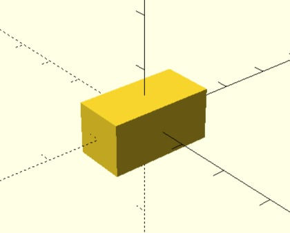
// Example 3, using the center parameter


    cube( size= [10, 20, 10], center= true );


// Things to notice here:
// 1) Now, the cube seems to be centered, no need to translate 
// Example 4, rotating a shape centered in the origin


    rotate ( [45, 0, 0] )
       cube( size= [10, 20, 10], center= true );


// Things to notice here:
// 1) Again, no ; between rotate and cube, the shapes and
//    its "modifiers" constitutes a single command.
// 2) The rotation is done as expected, 45 degrees around
//    X axis.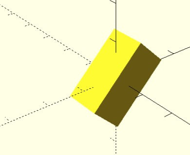
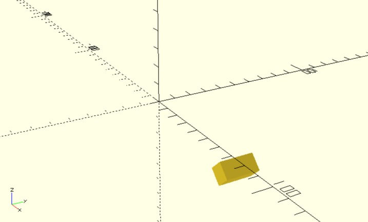
// Example 5, rotating a shape far from the origin
    rotate ( [0, 45, 0] )
     translate ( [45, 10, 10] )
       cube( size= [10, 20, 10] );


// Things to notice here:
// 1) This is not expected by common sense, however, the
//    rotation is good, it is rotating around the Y axis and
//    your shape is moving across the space!
//
// The lesson: if you want to put several shapes together
// it is strongly recommended that you do so on the origin
Another thing to notice from the former examples is that sometimes primitive parameters are just parameter values and sometimes they are a pair composed by a name= value, the reason for that is that openScad primitives uses default parameters, it means that if you do not specify a value for a given parameter a default value will be used. This programming technique where parameters are not given by its place in the list imposes that sometimes you have to explicitly say that the value you are specifying corresponds to a given parameter name. I will talk more about this when showing the module, however.
Other rendering primitives
You can use several primitives to render solids (among with 2D polygons and text that you can convert to 3D objects using the extrude primitive), the most common and useful ones are cubes, cylinders and spheres. The cylinder primitive is particularly useful because it allows you to specify the radius of both ends, the following are examples of those primitives and a few important remarks about them.
// Example 6, rendering a cylinder

cylinder( h= 30, r= 5);


// Things to notice here:
// 1) you specify the height and a radius, both ends will
//    have the same radius.
//
// 2) this solid is not centered by default
//
// 3) you should notice that the rendering quality is quite
//    poor, more on that next.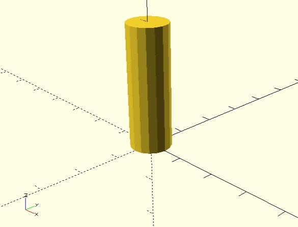
// Example 7, rendering a cylinder with different radius


cylinder( h= 30, r= 5, r1= 7, center= true);


// Things to notice here:
// 1) The center parameter is also present for the cylinder
//
// 2) You specify the height and the two radius, r and r1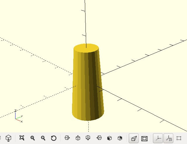
// Example 8, rendering a sphere


sphere( 20 );


// Things to notice here:
// 1) This shape is centered by default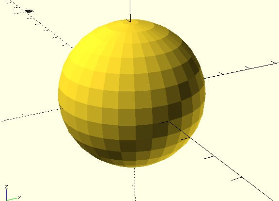
The former examples will allow you to understand solid rendering, we will review more options in the next posts, for now, an important issue regarding 3D design (it also applies to printing)
Faces, performance and quality
To achieve a better performance (in detriment of quality) 3D design software use faces to render shapes, and that is why you see the cylinders and spheres the way the look by default. The shapes are rendered using other simpler shapes (triangles, the same is true for 3D printing). If you want to achieve a better resolution, openScad has a property, called $fn ($ is because it is a system property, fn means face numbers). Face Number specify how many faces you are willing to use, the more faces, the smaller they will be and you won’t notice them achieving that way a better surface, the counter part of this is of course performance, if your designs are composed by many shapes and complex operations, the rendering time will increase notably. Here is the same sphere drown with a higher number of faces.
// Example 9, rendering a sphere with more faces


sphere( 15, $fn= 360 );


// Things to notice here:
// 1) The quality is much better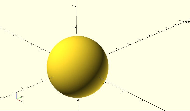
Besides the better aspect, having better surfaces are important to compose complex objects by combining them. That is the topic of the next post that will be released very shortly.
Stay tuned.


Comments